Installation & Debugging
Chapter 11 — Core Switch Security Hardening Design Guide
The installation and initial configuration of a core switch is a high-risk activity that requires careful planning, precise execution, and systematic verification at each step. Errors made during installation — such as incorrect cable routing, missing grounding, or applying the wrong configuration template — can result in security gaps that persist for years without detection. This chapter provides a structured installation procedure, environmental requirements, and a systematic debugging methodology for resolving the most common issues encountered during core switch security hardening deployments.
11.1 Installation Requirements — Real-World Scene
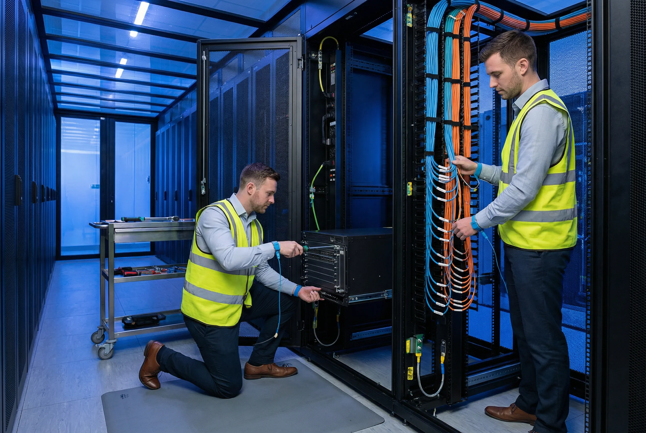
The installation scene below illustrates the correct professional approach to core switch installation in a production data center environment. Key elements visible in the scene include: engineers wearing ESD protection (wrist straps and anti-static mats), proper use of cable management tools, color-coded fiber optic cables with correct bend radius, organized vertical and horizontal cable managers, and a professional tool cart with all required installation tools staged and accessible. The data center environment features proper hot/cold aisle containment, raised floor for cable routing, and overhead cable trays for fiber management.
11.2 Environmental and Physical Installation Requirements
The physical installation environment must meet specific requirements before the core switch is installed. Failure to meet these requirements can result in hardware failures, security vulnerabilities, or operational problems that are difficult to diagnose after the fact. The following table defines the minimum environmental requirements and the verification method for each.
| Requirement Category | Specification | Minimum Standard | Verification Method |
|---|---|---|---|
| Temperature | Operating temperature range | 18°C – 27°C (64°F – 81°F) at inlet | Calibrated thermometer at rack inlet; continuous monitoring |
| Humidity | Relative humidity | 40% – 60% RH non-condensing | Calibrated hygrometer; data center DCIM system |
| Airflow | Hot/cold aisle containment | Front-to-back airflow; no hot air recirculation | Smoke pencil test; thermal imaging camera |
| Power | Redundant power feeds | Dual independent power circuits (A-feed + B-feed); separate PDUs | Verify circuit breaker labels; test each feed independently |
| Grounding | Equipment grounding | Chassis ground to rack ground bar; rack ground to facility ground | Continuity test with multimeter; resistance <1 Ω |
| Rack Space | U-space availability | Required U-space + 2U above and below for airflow clearance | Physical measurement; rack elevation diagram |
| Physical Security | Rack access control | Locked rack door; access log; CCTV coverage | Verify lock functionality; review access log; verify camera coverage |
| ESD Protection | Anti-static measures | ESD wrist strap; anti-static mat; ESD-safe tool kit | Test ESD strap with wrist strap tester before each use |
11.3 Step-by-Step Installation Procedure
The following installation procedure must be followed in sequence. Each step must be completed and verified before proceeding to the next step. The procedure is designed to minimize the risk of security gaps by ensuring that hardening controls are applied before the switch is connected to the production network.
| Step | Action | Verification | Notes |
|---|---|---|---|
| 1 | Verify hardware and software against pre-deployment checklist (Chapter 10) | All checklist items signed off | Do not proceed if any item fails |
| 2 | Install rack rails and mounting hardware | Rails level and secure; torque to specification | Use torque screwdriver; do not over-tighten |
| 3 | Install chassis into rack with at least 2 people | Chassis seated on rails; all mounting screws installed | Chassis weight may exceed 20kg; use lift if available |
| 4 | Connect chassis ground cable to rack ground bar | Continuity test passes; resistance <1 Ω | Ground before connecting power |
| 5 | Connect power cables (A-feed first, then B-feed) | Power supply LEDs green; no fault indicators | Verify correct feed assignment before connecting |
| 6 | Connect OOB management cable to console port | Console session established; login prompt visible | Use OOB management network only; not production network |
| 7 | Apply baseline hardening configuration via console | Config applied without errors; all hardening controls active | Use approved baseline template; do not modify during deployment |
| 8 | Verify AAA, NTP, and syslog connectivity via OOB | All supporting systems reachable and functional | Do not connect to production network until this step passes |
| 9 | Connect uplink interfaces to firewall/distribution (one at a time) | Each interface comes up; routing adjacencies established | Monitor syslog for unexpected events during each connection |
| 10 | Run post-deployment acceptance tests (Chapter 10) | All acceptance tests pass (100% pass rate) | Document all test results; obtain sign-off before traffic migration |
| 11 | Install physical security accessories (port blockers, tamper seals) | All unused ports blocked; tamper seals applied and photographed | Photograph all seals for baseline record |
| 12 | Complete installation documentation and sign-off | All documentation complete; both engineer and security team sign off | Retain documentation for audit; store in configuration management system |
11.4 Common Issues and Debugging Guide
The following table presents the most common issues encountered during core switch security hardening installations, their root causes, and the recommended debugging steps. This guide is intended to accelerate issue resolution and prevent engineers from inadvertently weakening security controls while troubleshooting.
| Issue | Symptom | Root Cause | Debugging Steps | Resolution |
|---|---|---|---|---|
| Management lockout | Cannot SSH to switch; AAA server unreachable | AAA server down; network path to AAA unavailable; misconfigured AAA | 1. Try console access; 2. Check AAA server status; 3. Verify OOB network path; 4. Check AAA config | Use console with local emergency account; restore AAA connectivity; verify fallback config |
| BGP session not establishing | BGP neighbor stuck in Active state | MD5 key mismatch; incorrect neighbor IP; ACL blocking BGP port 179 | 1. Check BGP auth key on both ends; 2. Verify neighbor IP; 3. Check ACL for TCP 179; 4. Verify routing to peer | Correct MD5 key; fix neighbor IP; update ACL to permit BGP |
| CoPP dropping legitimate traffic | Routing protocol flaps; management sessions timing out | CoPP rate limits set too low; traffic burst exceeds configured rate | 1. Check CoPP drop counters per class; 2. Identify which class is dropping; 3. Verify traffic is legitimate | Increase rate limit for affected class; use Chapter 9 CoPP calculator to recalculate |
| BPDU Guard false positive | Access port enters err-disabled; no rogue switch connected | IP phone or other device sending BPDUs; incorrect port type config | 1. Check what device is connected; 2. Verify port type (access vs. trunk); 3. Check device BPDU behavior | Configure portfast only on true access ports; disable BPDU on IP phone if supported |
| Syslog events not received at SIEM | SIEM shows no events from switch; switch syslog buffer filling | Syslog server IP incorrect; TLS certificate mismatch; firewall blocking syslog port | 1. Verify syslog destination IP; 2. Check TLS certificate validity; 3. Test connectivity to syslog port 6514 | Correct syslog destination; renew/replace TLS certificate; update firewall rules |
| TCAM exhaustion | Routes or ACL entries silently dropped; forwarding anomalies | TCAM capacity exceeded; too many routes, ACL entries, or features enabled | 1. Check TCAM utilization (show platform tcam); 2. Use Chapter 9 TCAM calculator; 3. Identify largest consumers | Reduce ACL entries; summarize routes; disable unused features; upgrade platform if needed |