Architecture Design
Chapter 4 — Core Switch Security Hardening Design Guide
Architecture design for core switch security hardening begins with a clear understanding of the network topology, security zone boundaries, and the trust relationships between zones. A well-designed architecture makes hardening controls easier to implement, verify, and maintain. Conversely, a poorly designed architecture creates ambiguity about where controls should be applied and makes it difficult to enforce consistent policies across the environment.
The reference architecture presented in this chapter is based on a dual-core switch design with MLAG redundancy, which is the most common deployment model for enterprise and data center environments. The architecture is organized into five distinct security zones, each with defined trust boundaries, access controls, and monitoring requirements. The design principles and zone model are applicable to other topologies (spine-leaf, collapsed core, chassis-based) with appropriate adaptations.
4.1 Typical System Topology
The reference topology illustrates the complete security architecture for a dual-core switch deployment. The topology is organized vertically by security zone, with the most trusted zones at the bottom (OOB management) and the least trusted at the top (Internet/WAN). All inter-zone traffic flows through defined enforcement points, and no zone can directly access another without traversing the appropriate security control.
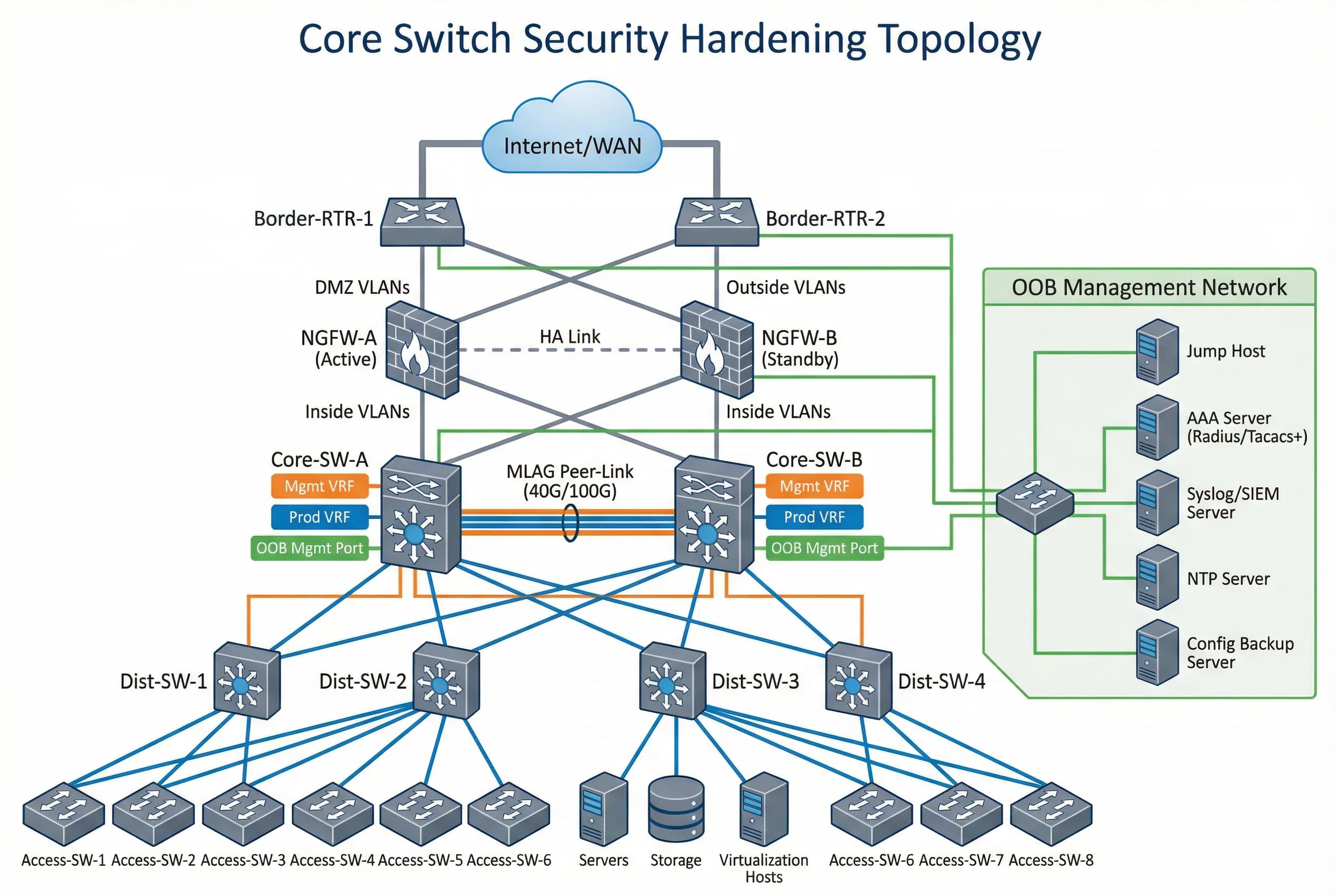
The topology demonstrates several critical design decisions. First, the OOB management network is completely separate from the production network, with its own switch, IP addressing, and access controls. Second, the core switches connect to the firewall pair via dedicated uplink ports that are assigned to the uplink VRF/VLAN, ensuring that management traffic never traverses production interfaces. Third, the MLAG peer-link uses dedicated ports with a separate VLAN to prevent production traffic from traversing the peer-link. Fourth, all management infrastructure (jump host, AAA, Syslog, NTP, config backup) is reachable only through the OOB management network.
Zone Definitions and Trust Boundaries
| Zone | Components | Trust Level | Access Control | Monitoring |
|---|---|---|---|---|
| Internet/WAN Zone | Border routers, ISP links, WAN circuits | Untrusted | Firewall policy; BGP prefix filtering; GTSM | BGP session state; prefix count; anomaly detection |
| DMZ Zone | NGFW pair, DMZ servers, load balancers | Semi-trusted | Firewall rules; ACL on core switch uplinks | Firewall logs; IDS/IPS alerts; flow analysis |
| Production Zone | Core switches (production VRF), distribution, access, servers | Trusted | VLAN segmentation; ACL; DAI; DHCP snooping | Performance metrics; CoPP counters; routing table |
| OOB Management Zone | OOB switch, console server, jump host, AAA, Syslog, NTP, backup | Highly trusted | Physical isolation; management firewall; source IP allowlist | All management access logged; AAA accounting; config change alerts |
| MLAG Peer Zone | Peer-link interfaces, MLAG keepalive | Trusted (internal) | Dedicated VLAN; no production traffic; peer authentication | Peer-link utilization; MLAG state; keepalive status |
4.2 Device Connection Diagram
The device connection diagram provides a rack-level view of the physical cabling and port assignments for the dual-core switch deployment. This diagram is essential for installation teams, as it specifies exactly which ports connect to which devices, what cable types are used, and how the OOB management network is physically connected. Color-coded cables distinguish between production, management, peer-link, and uplink connections.
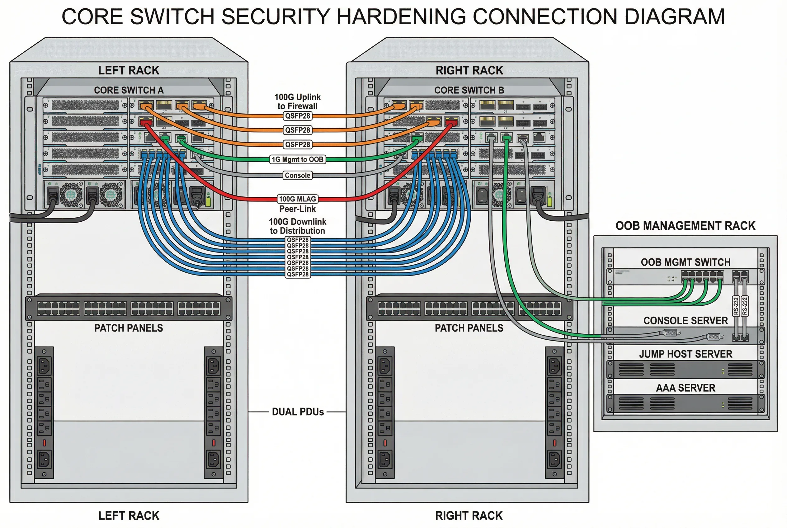
The connection diagram enforces several security design principles at the physical layer. Dedicated management ports (typically 1G RJ45) connect exclusively to the OOB management switch, never to production patch panels. Console ports connect to the console server via RS-232 cables, providing emergency access independent of all network connectivity. The MLAG peer-link uses dedicated high-speed ports (100G DAC cables) with no production VLANs allowed on the peer-link interfaces. Dual PDUs from separate power feeds provide power redundancy without creating single points of failure.
Cable and Port Assignment Summary
| Connection Type | Cable Color | Cable Type | Port Assignment | Security Notes |
|---|---|---|---|---|
| Uplink to Firewall | Orange | 100G QSFP28 SR4 or LR4 | Dedicated uplink ports (e.g., Eth1/1/1–1/1/4) | Assigned to uplink VRF; no management traffic |
| MLAG Peer-Link | Red | 100G DAC or AOC | Dedicated peer-link ports (e.g., Eth1/2/1–1/2/2) | Dedicated VLAN; no production VLANs; peer authentication |
| Downlink to Distribution | Blue | 100G QSFP28 SR4 or DAC | Production downlink ports (e.g., Eth2/1/1–2/1/24) | Production VRF; CoPP applied; routing auth enabled |
| OOB Management | Green | 1G Cat6 RJ45 | Management port (e.g., Mgmt0/1) | Management VRF only; source IP allowlist; no routing to production |
| Console | Gray | RS-232 RJ45 rollover | Console port (RJ45) | Connected to console server; emergency access only; session logging |
| Power | Black | C13/C19 power cord | PSU-A to PDU-A; PSU-B to PDU-B | Separate PDUs from separate power feeds; no single point of failure |
4.3 Security Zone Enforcement Points
Each security zone boundary has defined enforcement points where access controls are applied. The following table maps each zone boundary to the specific controls that must be implemented and verified. These enforcement points form the backbone of the hardening architecture and must be validated during acceptance testing.
| Zone Boundary | Enforcement Point | Controls Applied | Acceptance Test |
|---|---|---|---|
| Internet → DMZ | Border router + NGFW | BGP prefix filtering, GTSM, NGFW policy | Unauthorized prefix rejected; NGFW policy verified |
| DMZ → Production Core | Core switch uplink ACL | Inbound ACL on uplink ports; CoPP for control plane | ACL blocks unauthorized traffic; CoPP counters stable under load |
| Production → Management | Management VRF isolation | No route between production and management VRFs | Ping from production host to management IP fails; SSH from production fails |
| Management → Core Switch | Management firewall + source ACL | Source IP allowlist; SSH/HTTPS only; AAA authentication | Only jump host IPs can SSH; unauthorized source rejected |
| Core → Distribution | Downlink port security | Routing auth; DAI; DHCP snooping; STP guards | Rogue routing peer rejected; ARP spoofing blocked; rogue DHCP blocked |
| MLAG Peer Zone | Peer-link VLAN isolation | Dedicated peer-link VLAN; no production VLANs; peer authentication | Production traffic does not traverse peer-link; peer-link VLAN isolated |
4.4 High-Availability Architecture Considerations
High-availability architecture introduces specific security considerations that must be addressed during design. The most critical concern is ensuring that security policies remain consistent and effective during and after a failover event. MLAG and stacking designs synchronize forwarding state between peers, but security policy synchronization varies by platform and must be explicitly verified.
| HA Model | Security Sync Behavior | Manual Sync Required | Failover Test Requirement |
|---|---|---|---|
| MLAG (Multi-Chassis LAG) | Forwarding state synced; ACL/CoPP typically NOT synced automatically | Yes — ACL, CoPP, AAA, Syslog, NTP must be manually synced | Verify all controls active on both peers; planned failover test required |
| VSS/VSF Stack | Single logical switch; config applied once; synced automatically | No — but verify sync status after config changes | Planned failover test to verify management access continuity |
| Chassis Dual Supervisor | Active/standby supervisor; config synced; verify security-specific features | Partial — verify CoPP and ACL sync on specific platforms | Supervisor switchover test with management access verification |
| Active/Active Routing | Independent routing processes; each node must have identical config | Yes — full config sync required; use automation for consistency | Per-node acceptance test; failover test for each routing protocol |