Selection & Interfaces
Chapter 5 — Core Switch Security Hardening Design Guide
Selecting the right core switch platform is a foundational decision that determines which security features are available, how they can be configured, and what limitations must be worked around. Not all enterprise-grade core switches support the full spectrum of hardening controls described in this guide. Platform selection must therefore be driven not only by performance and port density requirements, but also by the security feature set, software quality, and vendor security posture.
This chapter presents the core product categories, their typical security feature capabilities, and the interface and port logic that governs how security zones are physically and logically implemented. The interface logic diagram provides a visual reference for understanding how port groups map to security zones and which security policies apply to each port type.
5.1 Core Product Introduction
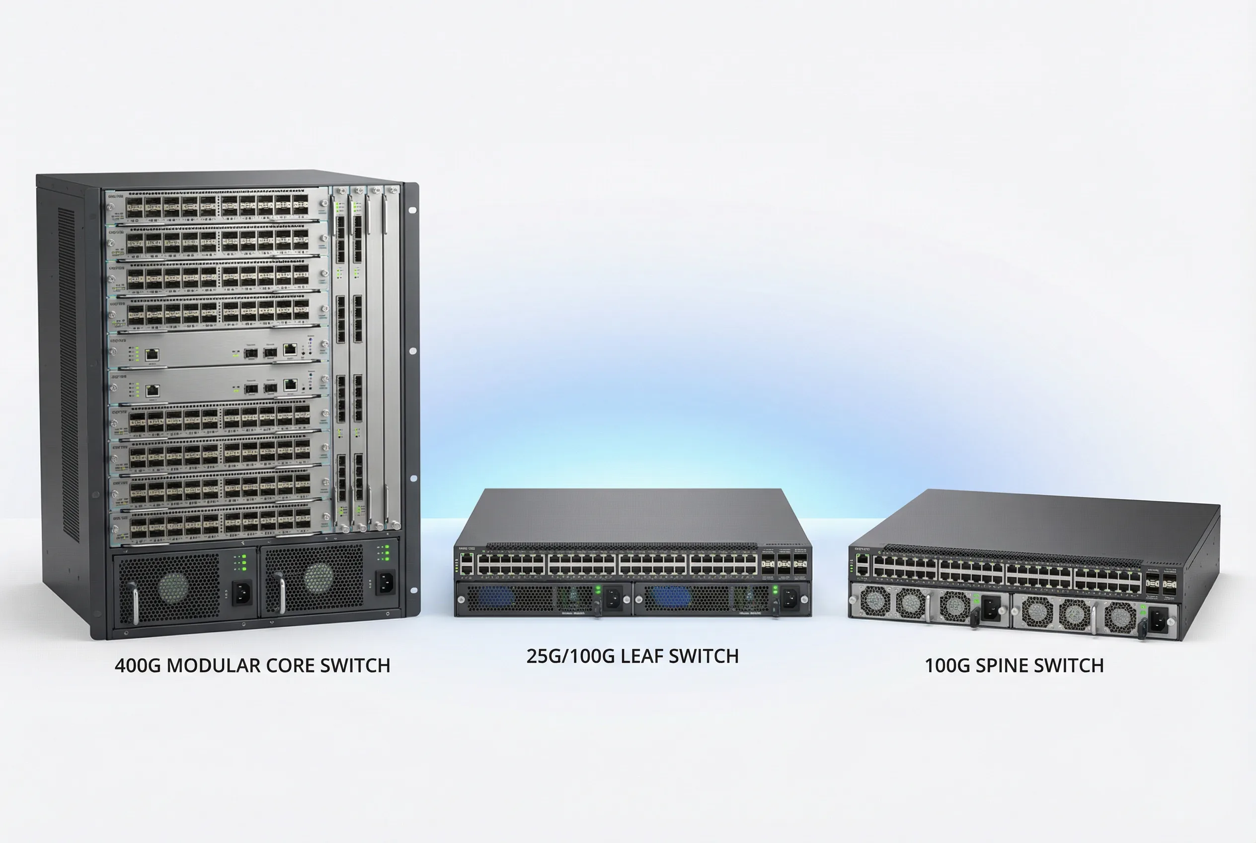
Core switches for security-hardened deployments fall into three primary categories based on chassis architecture and port density. Each category has distinct security feature capabilities, scalability characteristics, and operational considerations. The following figure illustrates representative products from each category.
Core Product Feature Comparison Table
The following table provides a comprehensive comparison of security-relevant features across the three core switch product categories. Features marked as "Full" are natively supported with hardware acceleration. "Partial" indicates software-only support or limited scale. "N/A" indicates the feature is not available on that platform category.
| Security Feature | Modular Chassis Core | Fixed High-Density | Spine Switch | Notes |
|---|---|---|---|---|
| Management Plane | ||||
| Dedicated OOB Management Port | Full | Full | Full | Standard on all enterprise platforms |
| Management VRF Isolation | Full | Full | Full | Verify VRF-aware management services |
| SSHv2 with Public Key Auth | Full | Full | Full | Disable SSHv1; enforce key-only auth |
| TACACS+ / RADIUS AAA | Full | Full | Full | TACACS+ preferred for command authorization |
| Role-Based Access Control (RBAC) | Full | Full | Partial | Spine switches may have limited role granularity |
| Session Timeout & Idle Disconnect | Full | Full | Full | Configure 10-minute idle timeout minimum |
| HTTPS REST API with TLS 1.2+ | Full | Full | Full | Disable HTTP; enforce TLS 1.2 minimum |
| gRPC/gNMI Streaming Telemetry | Full | Full | Full | Preferred over SNMP for modern deployments |
| SNMPv3 (AuthPriv) | Full | Full | Full | Disable SNMPv1/v2c; use SNMPv3 AuthPriv only |
| Control Plane | ||||
| Control Plane Policing (CoPP) | Full (HW) | Full (HW) | Full (HW) | Hardware-enforced CoPP on all platforms |
| BGP MD5/SHA Authentication | Full | Full | Full | Mandatory for all BGP sessions |
| OSPF MD5/SHA Authentication | Full | Full | Full | Mandatory for all OSPF areas |
| BGP RPKI Route Origin Validation | Full | Full | Full | Requires RTR server; verify TCAM capacity |
| GTSM (Generalized TTL Security) | Full | Full | Full | Apply to all eBGP and OSPF sessions |
| BFD (Bidirectional Forwarding Detection) | Full (HW) | Full (HW) | Full (HW) | Hardware BFD for sub-second failure detection |
| Data Plane / L2 Security | ||||
| DHCP Snooping | Full (HW) | Full (HW) | N/A | Spine switches typically L3-only; no L2 security needed |
| Dynamic ARP Inspection (DAI) | Full (HW) | Full (HW) | N/A | Hardware-enforced on all downlink ports |
| IP Source Guard (IPSG) | Full (HW) | Full (HW) | N/A | Verify TCAM capacity before enabling |
| 802.1X Port Authentication | Full | Full | N/A | Typically not required on core-to-distribution links |
| BPDU Guard / Root Guard | Full | Full | N/A | Apply to all downlink ports facing distribution |
| Storm Control | Full (HW) | Full (HW) | N/A | Hardware-enforced rate limiting per port |
| MACsec (802.1AE) Encryption | Full (HW) | Full (HW) | Full (HW) | Verify line card/ASIC support; performance impact |
| High Availability | ||||
| Dual Supervisor / NSF/NSR | Full | N/A | N/A | Modular chassis only; hitless failover |
| MLAG / Multi-Chassis LAG | Full | Full | Full | Verify security policy sync between peers |
| VSS / VSF Stacking | Partial | Full | Partial | Platform-specific; verify security feature support |
| Dual Power Supply (Hot-Swap) | Full | Full | Full | Mandatory for all core switch deployments |
| Dual Fan Tray (Hot-Swap) | Full | Full | Full | Mandatory; verify fan failure alerting |
5.2 Interface and Port Logic Diagram
The interface and port logic diagram provides a comprehensive view of how physical ports are organized into security zones, what naming conventions apply, and which security policies are assigned to each port group. This diagram serves as the definitive reference for port configuration and security policy assignment during deployment.
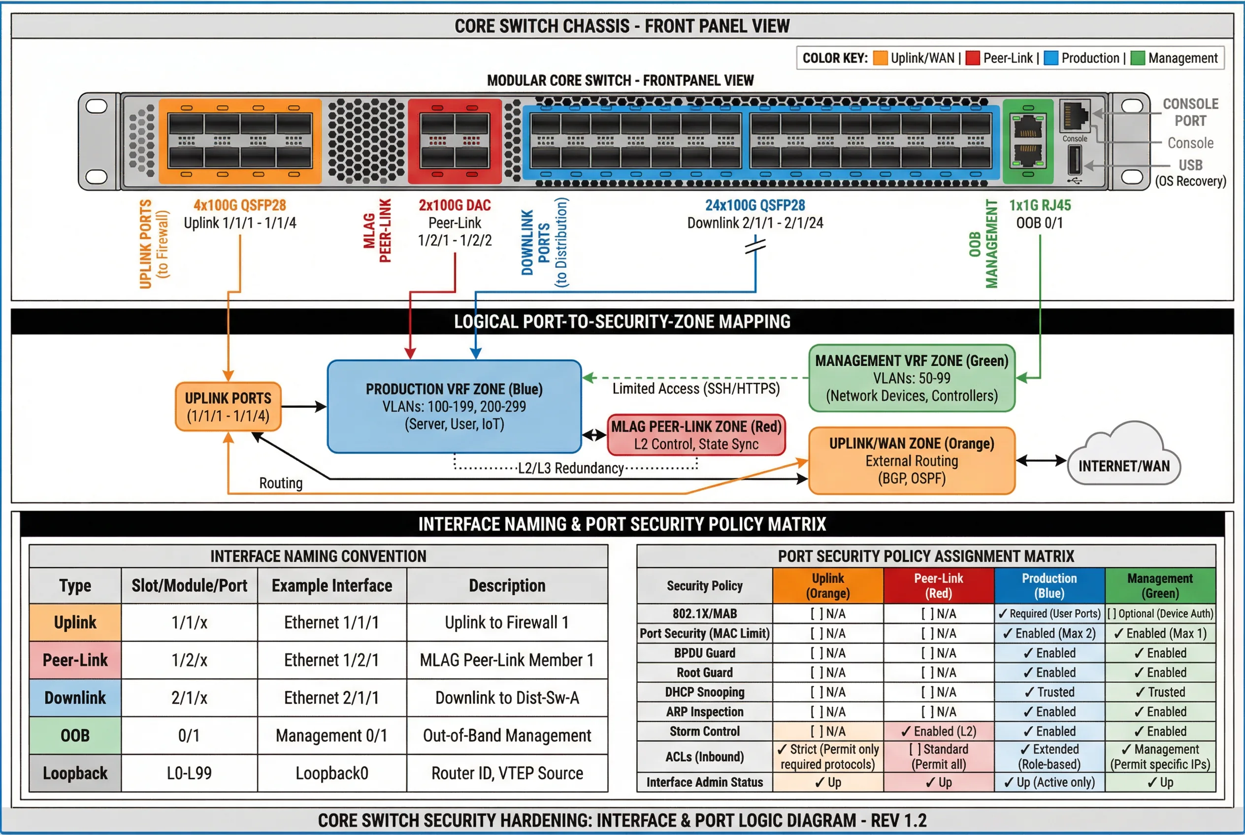
Interface Security Policy Assignment
The following table defines the mandatory security policies for each interface type. These policies must be applied consistently across all core switches in the deployment. Deviations from this table require documented risk acceptance and compensating controls.
| Interface Type | Uplink (Orange) | Peer-Link (Red) | Production Downlink (Blue) | OOB Management (Green) |
|---|---|---|---|---|
| VRF Assignment | Uplink VRF | Peer-Link VLAN (dedicated) | Production VRF | Management VRF |
| Routing Protocol Auth | BGP MD5/SHA | N/A (L2 only) | OSPF MD5/SHA | Static routes only |
| CoPP Applied | Yes — strict uplink policy | Yes — peer-link policy | Yes — production policy | Yes — management policy |
| ACL (Inbound) | Permit only required protocols; deny all else | Permit MLAG/LACP only | Extended role-based ACL | Permit only jump host IPs; SSH/HTTPS only |
| DHCP Snooping | N/A | N/A | Trusted (uplink) / Untrusted (downlink) | N/A |
| DAI | N/A | N/A | Enabled | N/A |
| BPDU Guard | N/A | N/A | Enabled | Enabled |
| Storm Control | N/A | Enabled (L2) | Enabled | Enabled |
| Port Security (MAC Limit) | N/A | N/A | Max 2 (distribution uplinks) | Max 1 |
| MACsec | Recommended for WAN links | Recommended | Optional (performance impact) | Recommended |
| Logging | Link state; BGP events; ACL hits | Peer-link state; MLAG events | Link state; routing events; ACL hits | All access; all commands; config changes |
5.3 TCAM Capacity Planning
TCAM (Ternary Content-Addressable Memory) is a finite hardware resource that stores ACL entries, routing table entries, ARP/MAC tables, and other forwarding state. Security hardening features such as extended ACLs, IP Source Guard, and RPKI route origin validation all consume TCAM entries. TCAM exhaustion causes security features to fail silently or fall back to software processing, which can dramatically impact performance and security posture. TCAM capacity planning must be performed before enabling security features in production.
| TCAM Consumer | Typical Entries Required | Priority | Planning Notes |
|---|---|---|---|
| IPv4 Routing Table (FIB) | 50,000–1,000,000 routes | Critical | Full Internet table requires 900K+ entries; verify TCAM bank allocation |
| IPv6 Routing Table (FIB) | 10,000–200,000 routes | High | IPv6 entries typically consume 2x IPv4 TCAM space |
| ARP / MAC Table | 32,000–256,000 entries | Critical | Scale with number of hosts; verify per-VLAN limits |
| ACL Entries (Inbound + Outbound) | 1,000–50,000 entries | High | Each ACE consumes 1–4 TCAM entries; count carefully |
| DHCP Snooping Bindings | 4,000–32,000 entries | Medium | Scale with number of DHCP clients |
| IP Source Guard (IPSG) | 4,000–32,000 entries | Medium | Consumes same TCAM as DHCP snooping bindings |
| RPKI ROA Cache | 50,000–200,000 entries | Medium | Requires dedicated TCAM bank on some platforms |
| QoS / CoPP Policies | 500–5,000 entries | High | CoPP entries consume TCAM; verify per-class entry count |